


![]()
The concept of charge storage was experienced even back to the days of the early Greeks when people observed the effects of static charge on insulating substances such as solid amber. However it took about 2,000 years before Pieter van Musschenbroek invented his "Leyden jar" in 1745.
The earliest Leyden jar used water as the internal "electrode" and large Leyden jars achieved capacitance values as high (for their time) as C = 1 nF. The amount of stored charge Q depends on this capacitance and the applied voltage
Q = C · V
When charged to a high voltage, e.g. from a static charge generator, the Leyden jar could be used to demonstrate brief sparks or an uncomfortable shock. The actual energy stored is
E = ½ · C · V 2
The Leyden jar proved interesting from a scientific perspective but required a more practical implementation. Modern capacitors are based on equal spaced parallel conductive sheets. These may be constructed as parallel conductive metal plates, although such plates may be rolled into a cylinder with no change in the general principle.
The capacitance C is proportional to the area of the plates and inversely proportional to the separation between them. In a perfect vacuum the capacitance is predicted from
C = ε0 · A/d Farads
where ε0 refers to the "permittivity of free space" and has a measured value of ε0 ≈ 8.85 · 10-12 Coulomb2 N-1 m-2 . For example, two 10 cm by 10 cm metal plates separated by 1 mm will have a capacitance of C = 88.5 pF. This is a relatively small value of capacitance compared to many high value capacitors of today (C >> 10,000 µF).
The easiest way to increase the capacitance value is to add an insulating dielectric material between the separated metal plates. These dielectric materials have higher permittivity values than ε0 and are usually characterized in terms of a "relative permittivity" εr defined as
ε = εr · ε0
The new increased capacitance then becomes
C = ε · A/d Farads
The final construction sandwiches the dielectric insulating material between the metal plates with some mild retaining pressure required to eliminate unwanted air-gaps. An improved approach is to "vapor deposit" a thin metal film over the insulating dielectric material and then connect electrically to this conducting layer.
Dielectric materials have a wide range of relative permittivity values. Some examples are
| Dielectric Material | Relative Permittivity
εr |
Application | Comment |
| Vacuum | ≡ 1 | Very high voltage capacitors e.g. V > 10 kV | Reference value by definition |
| Air | 1.00054 | Earlier variable capacitors, high voltage capacitors | Low values C > 500 pF |
| Paper | 3.5 | Early dielectric, low frequency | |
| Mica | 3 ~ 6 | Very stable, excellent high frequency performance | Relatively expensive |
| Teflon (PTFE) | 2.1 | Very stable, excellent high frequency performance | Also used as a PCB substrate for microwave circuits |
| Polycarbonate | |||
| Polystyrene | 2.4 ~ 2.7 | Excellent stability, high tolerance, linear -ppm/C | Non preferred |
| Polyester (Mylar) | 3.0 | ||
| Polyethylene | 2.25 | ||
| Polypropylene | 2.2 | ||
| Polyester Sulphide | |||
| FR4 (PCB) | 4.3 ~ 4.7 | ||
| Ceramic | < 75 | NPO, COG ±30 ppm BaTiO3 10 ~ 50% | Used for RF applications |
| COG | Used for RF Decoupling | ||
| <3,000 | BX, X7R ±15%, BaTiO3 90 ~ 98% | ||
| < 8,000 | Z5U +22%, 56%, BaTiO3 80 ~ 94% | ||
| < 18,000 | Z5V- +22%, 82%, BaTiO3 80 ~ 94% | ||
| Y5V +22%, -80% -30 < T < 85 C | |||
| Aluminum Oxide | 8.5 | ||
| Tantalum Dioxide | 86 ~ 173 | ||
| Niobium Oxide | 41 | ||
| Barium Titanate | 103 - 104 | ||
| Carbon Aerogel | |||
Large values of capacitance can be formed by adding many smaller capacitors in parallel. For example, The total capacitance CT for N capacitors C1 , C2, ... CN is equal to
CT = C1 + C2 + ..... + CN
If each capacitor has equal capacitance then the total capacitance is simply CT = N · C. This parallel combination can be realized by stacking multiple plate capacitors together

Note that the number of co-facing surfaces determines the number of capacitors. In the 5-stacked configuration shown above there are 5 capacitors for 6 metal electrodes (rather than 10 electrodes since both sides are used).
This construction is very well suited to ceramic dielectric capacitors. Unlike paper or plastic, ceramic can not bend so a cylindrical construction is not feasible.
Paper and plastic metal foil capacitors are easily produced as a rolled cylinder. This construction allows a long rectangular pair of electrodes to be wound into a compact format
Early cylindrical foil capacitors used thin aluminium foil ("tin foil") with a single point of connection to each wire lead connection. Unfortunately this approach introduced a long electrical path between each electrode connection and the inner capacitive contribution. The overall effect was to form an long transmission line with an open circuit at one end, resulting in low series resonant frequency. This limited applications to fairly low frequencies.
An improved approach was to deposit metal directly on the insulating dielectric and connect continuously along each end. This had the effect of "shorting out" this lengthy transmission with subsequent increase in series resonant frequency.
Although axial leaded components are suitable for hand assembly (e.g. as was once required for connecting components to the base sockets of electronic valves) this format is unsuitable for automated insertion into Printed Circuit Boards (PCBs). A rectangular format with parallel emerging leads was necessary, and could be accomplished by "squashing the cylinder body" into an approximate rectangle and attaching the leads at right angles to the capacitor's body

This construction is also suitable for Surface Mount applications - the wire lead electrodes are discarded and the component solders directly to the PCB copper tracks. This mounting method further reduces unwanted (parasitic) lead inductance, resulting in a reasonable RF capacitor, at least for High Frequency (e.g. F < 30 MHz) applications.
Early paper dielectric capacitors were widely used in high voltage electronic valve based products. These capacitors were relatively cheap and used a cylindrical construction with wax sealing. DC Voltage capability was around Vdc = 1,000 V and capacitance values around C = 0.05 µF were common.
Some long term failure modes were associated with these capacitor types and of course, wax and paper makes a great candle. An improved "Metallized Paper" construction is now used and has a "self healing" property if part of the paper dielectric "punches through" or shorts out (I guess the metallization layer sacrificially vaporizes before the paper dielectric catches fire.
These are based on a semi-cylindrical construction that takes a rectangular format. This avoids axial side exit leads as these are hard to auto-insert on a PCB. Electrical contact is made along the whole edge of the (aluminium) metal coating to reduce overall lead inductance. They are typically used for Electromagnetic Interference (EMI) suppression in high voltage AC (e.g. 230 Vac ) applications. Capacitance values are typically between C = 1 nF to C = 100 nF.
This example metallized paper capacitor appears to have a series resonant frequency of Fr ≈ 7 MHz for a capacitance value of C = 0.047 µF. The equivalent series inductance can be predicted to equal
Ls = 1 / [ (2 · π · Fr)2 · C ]
This equation predicts that Ls = 11.0 nH. This is extremely good for such a capacitor and might suggest useful RF applications. However this may not be advisable as other capacitors types can exhibit lower parasitic lead inductance combined with lower dielectric (AC) loss.
Early mica capacitors consisted of thin sheets of mica sandwiched between stacked metal plates under mechanical pressure. These were hermetically stable and generally stable with temperature but sometimes exhibited small capacitance "jumps" during temperature cycles. Presumably this was caused from a frictional effect between the mica and the metal plates during expansion and contraction. The solution was to deposit silver directly on the mica sheets, presumably to ensure a consistent electrode connection.
![]()
Modern mica capacitors are very stable but tend to be relatively expensive. Consumer equipment tends to avoid their use in favor of more cost effective varieties and choose design approaches that avoid the need for extreme capacitance stability with temperature and time.
Polycarbonate capacitors are often used for "power factor correction" with Florescent lamps. These mercury discharge tubes require a near constant current supply as opposed to standard AC mains voltage that is constant voltage (low impedance). Direct application of such an energy source would most probably cause a spectacular explosion as the terminal to terminal voltage of a florescent lamp may "clamp" at around 80 V and exhibit a series resistance as low as 1 Ohm.
Although a series resistor could be added this would waste a significant amount of power, thereby the reason for using an energy efficient light source. A series inductor is preferred as this provides a "ballast" and does not waste electrical power. It does cause a phase lag between current and voltage and it is preferable to remove this imbalance. A capacitor, placed across the series inductor-lamp combination resonates with this inductance (at the AC mains frequency e.g. 50 Hz or 60 Hz) so that the overall combination appears to be resistive.
Typical capacitance values range from C = 2 to 30 µF. Since the capacitor is placed directly across the AC mains voltage, reliability and internal protection (e.g. fuses) is of paramount importance.
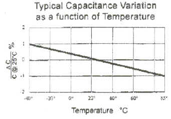
Polycarbonate capacitors are also used in low cost, low power applications. They tend to have reasonable temperature stability and low dissipative loss up to moderate AC frequencies. Although not suitable for RF applications, they are useful in switch-mode power supplies operating at switching frequencies up to several hundred kHz.
Typical capacitance ranges are C = 100 pF to 0.047 µF

Note the capacitance temperature sensitivity is minimized at room temperature and becomes gradually negative at the temperature extremes. We also note that the dissipative "loss tangent" tanδ ~ 22 · 10-3 at F = 300 kHz. This dissipative loss is related to capacitor "Q" and equivalent series Rs or parallel Rp resistance according to
Xc = 1/( 2 · π · F · C ) Ohms
Rs = tanδ · Xc Ohms
Rp = Xc / tanδ Ohms
Q = tanδ -1 = Xc / Rs = Rp / Xc
If we assume a capacitance value of C = 10 nF with a loss tanδ = 22 · 10-3 at F = 300 kHz of we predict Xc = 53 Ω, Rs = 1.2 Ω
or Rp = 2.4 kΩ and Q = 45.
Polyester capacitors are intended for general decoupling and DC blocking applications where accurate capacitance values or stability is not critical. Typical capacitance values range from C = 4.7 nF to C = 15 µF. They have relatively low dielectric loss and are suitable for low to moderate frequencies (below a few MHz).
The polyester dielectric is an extremely good insulator as can be seen from the parallel leakage resistance values in this example capacitor family (R > 15,000 Meg Ohms).
We note that the actual capacitance has a frequency dependency and can fall by several percent at frequencies as low as 100,000 Hz. This is presumably due to a "dielectric memory" effect. We also note the temperature stability is somewhat average and can also fall several percentage over -30° C < T < 60° C
Once again the construction is intended to minimize stray (parasitic) lead inductance. If we use the 2.2 µF capacitor as an example, with a series resonant frequency shown below as Fr ~ 800 kHz, we predict a stray lead inductance of Ls ~ 18.0 nH. For comparison, the 56 nF capacitor with Fr ~ 6.5 MHz has a predicted stray lead inductance of Ls ~ 10.7 nH. Both these outcomes show good medium frequency decoupling potential. The actual effective series resistance Rs is also quite low, e.g. Rs < 0.03 Ohms for the 2.2 µF example.
Polypropylene capacitors have many applications, ranging from small capacitance high quality components to high current for AC mains (line) 230 Vac or 115 Vac electromagnetic suppression capacitors or very high current AC motor start / run applications.
Small electronic circuits benefit from low dissipation loss and low dielectric absorption. This last characteristic represents a "memory effect" whereby the dielectric material retains some residual charge. The effect of dielectric absorption is not beneficial - capacitors with high dielectric absorption exhibit high loss at higher frequencies so small to medium value polypropylene metallized film capacitors are well suited to circuits that demand a high quality component (e.g. loop filter capacitors used in Phase Lock Loop frequency synthesisers)
The construction used in this component example (WIMA) uses a stacked plate arrangement.
We also see the tanδ parameter is favorably low - tanδ ≤ 10-3 @ F = 1 MHz for a C = 1 nF version. This corresponds to a "Quality Factor" of Q ≥ 1000.
Evidence of this low dissipative and absorptive loss extends well into the VHF range. We note a series resonant "notch" frequency of Fr = 300 MHz for a C = 33 pF capacitor and a minimum impedance value (effectively its series resistance) of 0.2 Ohms.
 Note: Ls = 1 / [ (2 · π
· Fr)2 · C ]
Note: Ls = 1 / [ (2 · π
· Fr)2 · C ]
Using the previous equations we predict X = 16 Ohms, R = 0.2 Ohms, L = 8.5 nH.
Polypropylene metallized capacitors are quite versatile and also find applications in places that demand a rugged component capable of sustaining full AC mains (line) voltage with potentially high associated AC currents.
The low dissipation factor of polypropylene is essential. Internal losses in high voltage and current situations is converted to heat. Excessive temperature rise would lead to capacitor failure with potentially catastrophic results!

In this application the exact capacitance value is much less important so temperature coefficients are not constrained to any degree.
![]()
Similar performance attributes are required for mains interference suppression
The loss tangent values remain very low, and the insulation integrity is excellent
The AC ripple current handling capability can be as high as 2 Amps for the 3.3 µF version. The temperature coefficient is relatively high but motor start and electromagnetic suppression tasks do not require low temperature coefficient performance.
The electromagnetic suppression applications require low parasitic lead inductance combined with low impedance.
We see the C = 100 nF capacitor has a resonant notch around 6.5 MHz with a minimum impedance less than 0.1 Ohms. The equivalent series parasitic lead inductance is predicted to be L = 6.0 nH (an excellent low inductance outcome)

Polystyrene capacitors have traditionally been used as a substitute to high stability mica capacitors for IF and RF applications requiring high capacitive tolerance and low, monotonic temperature characteristics (usually slightly negative at - 150 ppm / C)
|
CHARACTERISTICS |
|
TYPE LCR (Standard Polystyrene)
|
|
| Capacitance | 25pF - 200,000pF |
| Capacitance Tolerance | +- 20%,10%,5% |
| +- 2.5% or +- 1pF min | |
| Tolerances closer than 2.5% are available | |
| Voltage (DC working) | 30, 63, 160, 400, 630V |
| Temperature Range | -40C to +85C |
| Temperature Coefficient | N 150 +- 50 ppm/C |
| Power Factor | <0.0005 |
| Insulation
Resistance (dry) |
>10,000,000 Moh |
Polystyrene capacitors use a cylindrical construction with aluminium foil electrodes with a single welded connection to a wire lead. They have relatively high series resistance and are not suitable for low impedance applications such as decoupling.
Although polystyrene has good dielectric properties it is discouraged. Polystyrene capacitors are relatively expensive and the actual dielectric material is becoming unavailable.
"polystyrene: Although polystyrene material is no longer available LCR have acquired sufficient material to manufacture at the present scheduled rate for a minimum of 15-20 years"
Polystyrene capacitors, it seems, belong now to a bygone era. Excellent alternatives are available as I hope this web chapter has shown. Additionally, the high parasitic lead inductance arising from the cylindrical construction with single point electrode connections are avoided in other varieties. The high component cost of polystyrene capacitors can also be avoided.
Summary: I would not recommend polystyrene capacitors for new design. Although some manufacturers may point towards their exceptional virtues, if such virtues are required it may well be better to ask if the design approach shouldn't be done a different way. For example, if a design needs a "free running oscillator" with exceptional frequency stability why not replace it with a VCO and use a Phase Lock Loop with a XTAL or TCXO oscillator reference? A similar alternative applies to filters and timing circuits - why not consider a more modern architecture that relaxes critical requirements and places high tolerance needs in the hands of commonly available and cost effective components that are specifically intended for this. After all, in a commercial setting, designing obsolescence into a new product is not seen as a good idea.
Ceramic capacitors are possibly the most versatile variety available today. Unlike previous paper and plastic dielectrics, ceramic dielectric contains and extremely wide range of varieties with relative permittivity values ranging from about 30 to over 18,000.
An extra feature of the ceramic dielectric (unlike paper and plastic film implementations) is its ability to be combined with other compounds such as Barium Titanate (BaTiO3) and Calcium Zirconate, Strontium Titanate and Magnesium Titanate to greatly influence the dielectric permittivity and temperature characteristics.
As the previous graph shows, "NPO" mixtures result in excellent temperature stability whereas "Z5V" mixtures produce much greater relative permittivity (K ↔ εr) at the expense of temperature stability. These high K mixtures are well suited to decoupling applications that require high capacitance values (e.g. C > 1 µF) without any great concern for absolute capacitance value whilst NPO types are well suited to RF applications where capacitance value is of prime importance.
(Note: Porcelain capacitors are similar to NPO types but have extremely low loss and are well suited to high power (> 100 Watt) RF and microwave applications).
The Y5V ceramic composite dielectric offers extremely high permittivity in exchange for relatively poor electrical performance and a restricted operating temperature range. The capacitance variation is +22%, -82% over a temperature range of T from -30 C ≤ T ≤ +85 C
The Y5V dielectric is intended for high capacitance values required for decoupling where the actual capacitance value and quality is relatively non critical. They tend to have very high dissipative loss (this can actually be an advantage for decoupling usage as accidental resonance with other parallel capacitors is minimized)

SMD sizes cover the standard ranges of 0201, 0402, 0603, 0805, 1206 and 1210 with capacitance range within 1.0 nF ≤ C ≤ 22 µF.
We can also observe a strong temperature dependency, as well as a strong reduction in capacitance with applied DC bias voltage (like a Varicap diode - I wonder if this property could be used for tunable audio filters!)

We can see good low impedance behavior however, attaining values of |Z| < 0.1 Ohms. Note the massive reduction in capacitance with applied voltage though - as high as -90% at % DC rated voltage. This may need to be taken into account as the capacitor may not exhibit the minimum value required when DC voltage, inevitably, will be present.
The example 0.1 µF 0603 capacitor value has a series resonant frequency of about 3 MHz, inferring an effective series parasitic lead inductance of Ls ≈ 28 nH.
The X7R ceramic composite dielectric offers somewhat better stability over an extended temperature range. The temperature variation in capacitance is C ±15% for temperatures with the range -55 C ≤ T ≤ +125 C.
Capacitor values are typically within 100 pF ≤ C ≤ 22 µF. The main applications are decoupling and DC blocking. The dissipative losses are relatively high but of less importance in these applications.

We can observe the capacitance value to posses a non linear temperature dependency as well as reducing in value with increasing AC frequency
Actual series resonant frequency is quite high, for example the 1,000 pF, 0805 version has a series resonant frequency F ≈ 150 MHz with a minimum impedance of |Z | < 0.5 Ohms. This corresponds to a parasitic lead inductance of Ls ≈ 1.1 nH.
The X5R composite ceramic dielectric is also intended for non critical decoupling and DC blocking. The capacitance variation is C ±15% over a temperature range of -55 C ≤ T ≤ +85 C but usually 0%, -15%
Capacitance range is typically 100 pF ≤ C ≤ 100 µF.
The X7S composite ceramic dielectric offers slightly worse tolerance than X5R and X7R of C ±22% but with an extended temperature range of -55 C ≤ T ≤ +125 C. Typical capacitance ranges are within 33 nF ≤ C ≤ 22 µF

As before, the capacitance depends on temperature and frequency. A voltage dependency is also likely
Parasitic lead inductance remains usefully low. We see the same resonant frequencies as X5R and X7R, i.e. Ls ≈ 1.1 nH
This lower permittivity dielectric compound has excellent stability characteristics and is well suited for high frequency operation into the microwave region (recent definitions for "UHF" identify frequencies in the range 300 MHz < F < 3 GHz, previous definition for "microwave" referred to frequencies F > 1 GHz. COG Capacitors have been used usefully up to 5 GHz)
Typical capacitance range is 0.5 pF ≤ C ≤10 nF.
The COG (NPO) ceramic composite dielectric has excellent electrical properties and stability as can be seen in the following graphs
The COG capacitors also offer extremely low parasitic lead inductance and high self (series) resonant frequency combined with low minimum impedance (i.e. series resistance).
We can observe a series resonant frequency of Fr ≈ 150 MHz for a 1,000 pF, 0805 version along with a minimum impedance of |Z| < 0.1 Ohms. The associated parasitic lead inductance is therefore Ls ≈ 1.1 nH. This is an excellent result and represents the lowest parasitic lead inductance of all capacitors investigated so far.
Aluminium oxide electrolytic capacitors provide very high capacitance per volume ratios but tend to have relatively poor dielectric properties. Although significant technology improvements have occurred over time, electrolytic capacitors tend to have high effective series resistance and significantly low parallel leakage resistance (an so current).
The construction is similar to cylindrically wound (metallized) paper layer capacitors with two primary differences
| The paper is soaked in a conductive electrolyte solution - it's function is therefore to separate rather than to insulate | |
| The paper is not metallized and aluminium foil is used for polarized (+) anode and (-) cathode terminations | |
| This aluminium foil has an insulating oxide covering that forms the dielectric - this forms two capacitor interfaces connected in series |
An excellent link for a physical description of electrolytic capacitors can be found at
http://electrochem.cwru.edu/ed/encycl/art-c04-electr-cap.htm
Some example SMD electrolytic capacitors from Panasonic can be seen below. Capacitance values range from 10 µF to 6,800 µF in this series (voltage ranges up to 16 Volts only are shown).
The first noteworthy item is the high series resistance compared to previous capacitor types - a typical characteristic of electrolytic capacitors. A 22 µF capacitor, for example has an impedance of |Z| = 1.35 Ohms at F = 100 kHz. Given that the capacitive reactance would be Xc = 0.072 Ohms at this frequency, this impedance will predominately equal the capacitor's series resistance. The losses associated with this series resistance generate internal heat - this imposes a "ripple current" rating which, in this example, is only 90 mA.
The power lost is predicted from
P = I2 · Rs
This equation suggests that 11 mW of heat will be internally generated at an RMS ripple current (AC or AC superimposed on DC) of 90 mA.
It is also important to observe the effects of leakage currents in high impedance or sensitive circuits. This leakage current can be as high as 3 µA or C · V, whichever is highest.
A further unwelcome characteristic is the severe reduction in capacitance at low temperatures; this can reduce by a factor of 4 times. The series resistance will also increase sharply (not shown here)
Electrolytic capacitors remain popular and represent a very cost effective capacitor type for non critical, medium temperature range applications.
Tantalum oxide capacitors are based on a similar principle of operation to electrolytic capacitors but use a "dry electrolyte" instead of a "wet electrolyte". They are more expensive but offer lower leakage, much lower series resistance and a much wider temperature operating range.

In comparison to the previous electrolytic capacitor example where C = 22 µF and Rs = 1.35 Ohms, this corresponding C= 10 µF Tantalum capacitor has a series resistance ranging from Rs = 0.3 Ohms down to Rs = 0.03 Ohms depending on "TC" or "TCO" series, in this range.
Typical example components from Cooper Bussmann

Maximum Working Voltage 2.5 V
Capacitance Tolerance -20% to +80%
Temperature Range -25C to 70 C
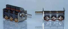
Although modern solid sate RF power amplifier design favors broad band, fixed matching design approaches, narrow band, manually tuned situations still apply in some areas of development. Electronic valve transmitters, for example, are usually, if not always based on narrow band, manually adjusted output matching networks operating at high DC and RF voltage levels (e.g. Vs > 600 Volts).
Some companies produce manually tuned capacitors specifically for these applications. The target audience includes radio amateur construction hobbyists and people involved in the design and construction of scientific apparatus. The electrical and mechanical quality of these components can be excellent as the following images suggest
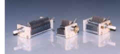
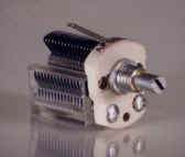
Selection from http://www.orenelliottproducts.com/index.html
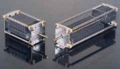
The air dielectric implementation has extremely low loss allowing high RF power handling capability that can exceed 1,000 Watts of RF energy. However low power receiver applications are also catered for, as can be seen in the following low frequency, medium capacitance versions (The variable capacitor on the right looks like a 30 - 365 pF variety)
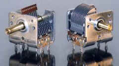
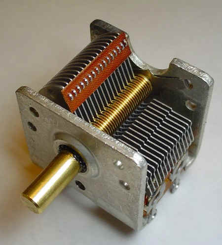
In many cases, a "ganged" multiple capacitor may be needed. For example, a "superhet" receiver requires simultaneous tuning of RF and LO circuits. In some cases an additional RF amplifier stage may be used, suggesting the need for a three section ganged capacitor (below)
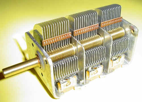
These three ganged capacitors appear to have equal capacitance sections based on the size of each "stator" and "rotor" pairing. I guess they could have been used, in principle, for a "Tuned Radio Frequency" or TRF receiver as used in early medium wave radio's in the 1930's
Although artistic in appearance to some degree, these components are unsuitable for cost effective, high volume products. High RF power applications based on semiconductor power amplifiers typically (or always) use fixed matching networks for power transfer from device to load. Many LDMOS devices, for example can produce upwards of 200 Watts from a 28 Volt supply and cover a percentage bandwidth as high as 30% without tuning. These can be easily combined as power modules to produce a total output power exceeding 1 kW without any major difficulty. Even AM transmitter stations operating at 50 kW can be implemented completely with a solid state approach.
Although some high power low volume requirements will probably remain for some time, the need for low frequency receiver variable capacitors seems hard to justify, especially when air dielectric types are expensive and bulky. Plastic dielectric types are often used in very low cost pocket AM radios
However, high performance AM-Shortwave-FM Radios use Phase Lock Loop (PLL) technology (and frequency up conversion on AM-Shortwave to remove unwanted image responses) and so avoid the need for manual tuning. This technology also allows "station memory buttons", station scanning etc, not available in a manual tuned approach.
As time progresses, this design approach may become equally competitive with the manually tuned radio, even if the convention frequency down conversion approach is retain. The future for manually tuned capacitors does not, therefore, seem to be favorable.
Admittedly, I was surprised to find quite a selection of these! Here are some mica compression trimmer capacitors, reminiscent of the 1930 valve radio in a cow shed days!
The use of a plastic dielectric is still popular (although I prefer design approaches that avoid the need for manual adjustments)
 TYPES
of Dielectric That May Be Used
TYPES
of Dielectric That May Be Used
- High temperature PTFE
- Standard PTFE
- Polypropylene
- Polyamide
- Polycarbonate
- Polyphenylene sulfide
Ceramic dielectrics are also used 
For very high frequency microwave usage, Sprague-Goodman etc offer extremely low loss glass-sapphire piston types
As we have seen the world of capacitors is richly populated with many varieties, each optimized for specific applications. The earliest commercial "paper dielectric" capacitors are still used but with advantageous properties such as "self healing" incorporated. Three broad categories are available for fixed capacitors
| Rolled film dielectric types - paper, polyester, polycarbonate, polypropylene, polyphenylene, polystyrene | |
| Stacked layer (monolithic) construction - ceramic, also some plastic dielectrics | |
| Polarized metal oxide dielectric - electrolytic, tantalum, Aerogel Foam |
Paper and plastic film capacitors find a wide range of applications ranging from high power AC mains usage (motor start/run, power factor correction) to high stability audio and timing circuits. Accurate and stable RF characteristics are also available in polystyrene dielectric fabrications but these capacitors are loosing favor due to high relative cost, excessive lead inductance and potential availability issues associated with polystyrene foil.
Ceramic capacitors have come a long way since their first introduction about half a century ago. They use a composite ceramic dielectric combined with rare earth metal oxides such as Barium Titanate and offer moderate permittivity, highly stable dielectrics for RF applications as well as mixtures that exhibit extremely high relative permittivity, less temperature stable performance that is well suited for decoupling and DC blocking.
We also observe a very high voltage sensitivity in high permittivity types such as Y5V (-90% at rated DC voltage) and to a lesser extent in X7R mixtures.
The highest capacitance per volume ratios are achieved using electrolytic or tantalum oxide (polarized) capacitor implementations. Of these, the aluminium electrolytic versions have relatively high series resistance, significant leakage current and fairly low AC current handling capability. Tantalum capacitors are superior in all these aspects but tend to be relatively expensive. A significant design trend in recent years has been to replace tantalum capacitors with high permittivity ceramic capacitors whenever possible. These ceramic capacitors appear to be in a continuing process of performance advancement and represent a very cost effective solution.
Super capacitors (electrolytic capacitors) are another recent invention and offer capacitance values exceeding many Farads. These are intended to augment battery applications, e.g. to provide temporary backup power etc.
Finally, variable capacitors are still in use and may use plastic or ceramic dielectric material. The need for any manual factory adjustment is contrary to Design For Manufacture (DFM) philosophies but cheap low cost products may need to resort to this human intervention prior to shipment. The need for manual tuning seems to still haunt the low cost AM and FM radio market, but many of these now offer electronic push button or automated tuning capability. Some specialized high voltage applications may exist but my guess is that the future market outlook for variable capacitors (requiring human manual intervention) is grim. This component type is not in a growth market.
But all in all, this Component Universe heralds capacitors in high regard. They represent a very diverse bunch, each variety having its special attributes, quirks and personality.
I hope this web chapter has been informational and shown the many options available in capacitor selection. In many cases, a particular circuit requirement can be meet with a variety of capacitor types - the final selection may come down to price, availability and personal preference.
![]()
Return to: A Component Universe
or: Ian Scotts Technology Pages
© Ian R Scott 2007 - 2008