
![]()
I had been pondering the limitation inherent in standard Frequency Modulation (FM) Theory for quite some time. The standard modulation approach, for example, is to consider FM to be represented as the rate of change of phase with respect to time for a vector following a circular route on an IQ signal representation plane. Conversely, the demodulation process is seen as an integration of phase determined from an arctangent function of Q/I where I <> 0 with various modifications depending on which IQ quadrant the signal vector is in.
It has always bugged me that a complex IQ signal representation should not have a complex frequency FM interpretation. Why would anyone accept a complex to real conversion - surely this represents an obvious loss of information.
This motivated me to consider a complex to complex "Non Linear Transformation" or mapping between complex I + j Q base-band to "sigma + j omega" modulation domain. This immediately encompassed traditional theory as a subset case with sigma = 0!
I am unsure if "mathematics" has ever been patented before. It took two years and two patent attorneys to accomplish this but now the patent is in the public domain.
I thank two other contributors for this project;
| Refik Shadick - Provided DSP code on a FPGA platform based on my mathematical representation | |
| Mark Siddall - Oversaw RF hardware for one communication transceiver project incorporating these mathematics. |
The actual signal representation is best seen as a conceptual analysis tool - it may not generate new, novel or useful modulation formats (this was not my original intention). It is well known that problems usually simply in complex variable and given that the conventional FM interpretation is a special subset case of complex frequency offset estimation, (and clumsy!) it seems to me, at least, that the patent and its message have intrinsic value.
These following pages are images direct from US patent application US 20060230089 that I applied for after developing the mathematical theory framework. I will add brief explanations and comments after each page as patents need to be written in a particular way (for Intellectual Property - IP - protection) rather than for the purpose of clear explanation!
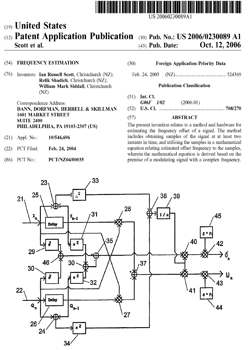
The demodulation is "instantaneous" in a mathematical sense, but physical hardware must add time delays of course. These are usually become vanishing small however. The flow diagram shown above just represents the steps identified in the mathematical discrete time domain (approximation) for demodulation, i.e. s{n × dt} -> Viq{n × dt}. (I drew these pictures in Microsoft Works so they are a bit clunky).
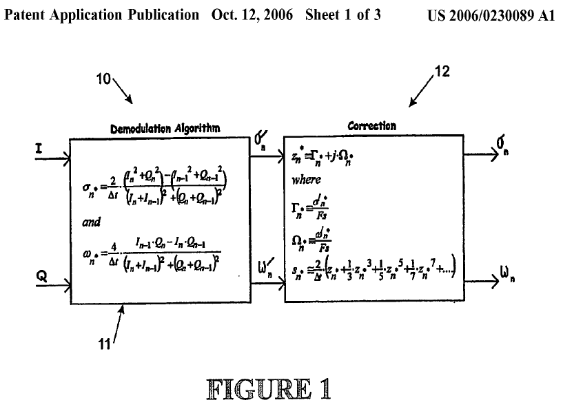
This picture shows the discrete time domain Non Linear Transform from Complex IQ base-band to Complex Frequency Modulation (sigma' and omega'). This represents demodulation from I and Q discrete time domain sampled signals. The effect of the discrete time domain approximation (compared to the exact continuous time domain conversion) is to introduce demodulation distortion. This distortion is completely predictable and I include another correction transform that eliminates this distortion to arbitrary low levels. (Up to a certain limit - i.e. the maximum time step dt is equal to dt = 1 / [Fs × pi] )
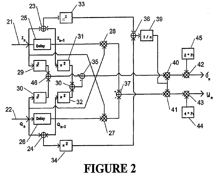
Simply a repeat of the cover page!
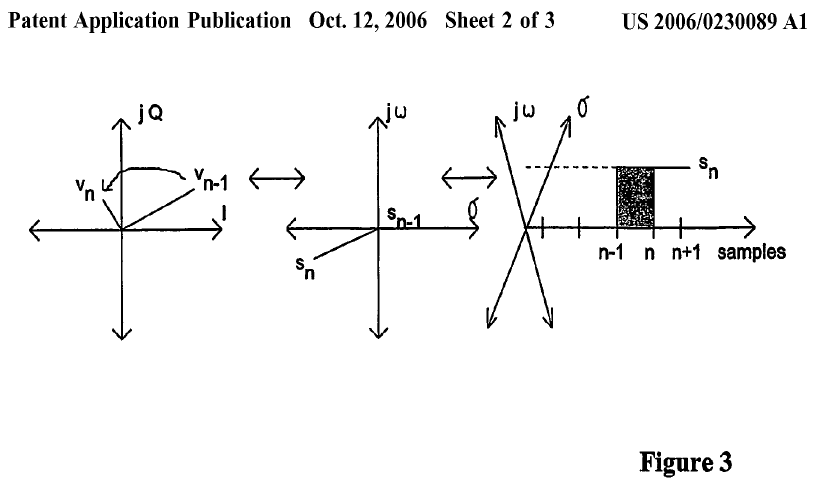
Figure 3 shows complex IQ base-band to complex frequency non linear mapping with discrete time samples (2 adjacent IQ samples produce one complex frequency result). The complex freqiency result sn can then be seen as a progressing rectangle (vector) projecting a complex trail over a complex frequency plane.
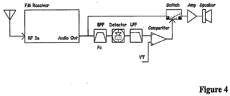
Figure 4 shows a conventional noise mute approach used in FM receivers (often PMR VHF and UHF voice application).
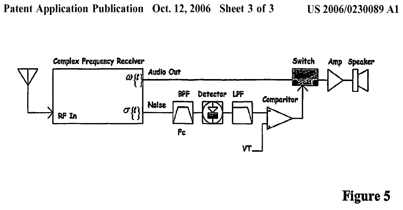
The use of the real sigma component for noise muting provides several advantages,
| Modulation desensing is reduced as the real component of "s" doesn't contain modulation | |
| The Band Pass Filter (BPF) can even be removed! |
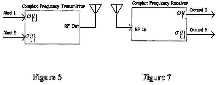
In principle, a full complex frequency transceiver has two channels available for communication (e.g. stereo capability). These two channels are exactly orthogonal.
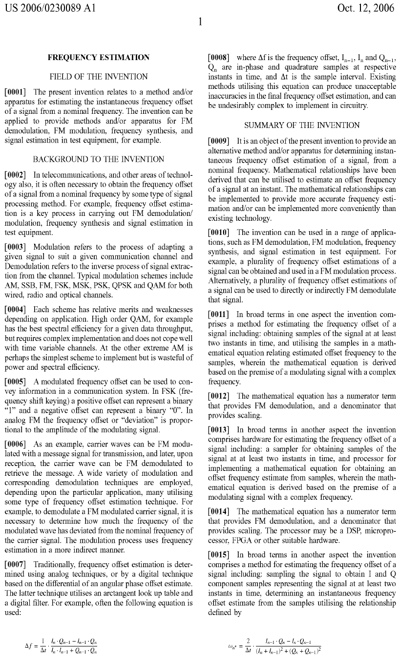
Note: A conventional algorithm has been used but is wrong. The correct demodulation algorithm is presented instead.
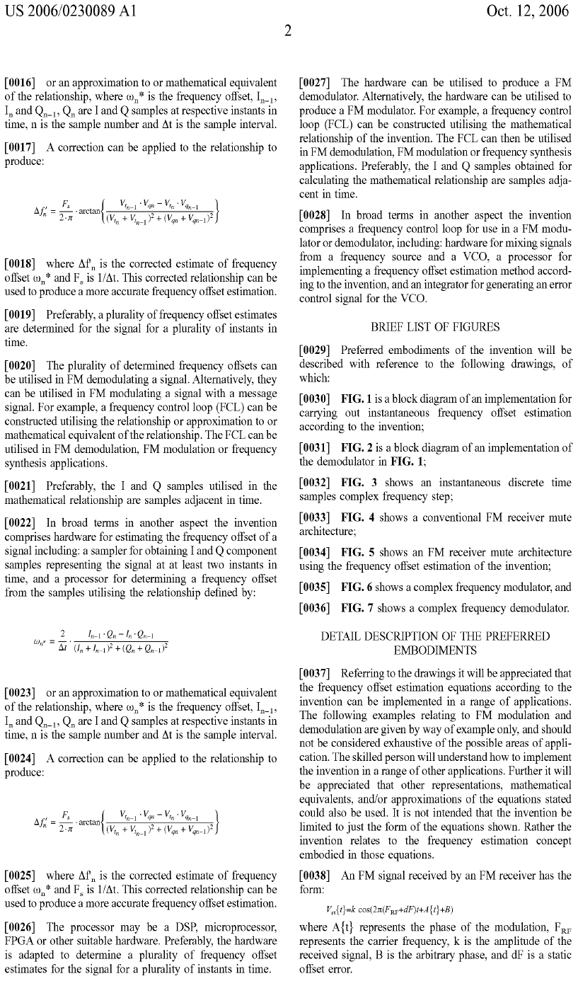
The effect of discrete time sampling is to produce an arctangent form of distortion. This has a complex polynomial based correction algorithm as will be shown later.
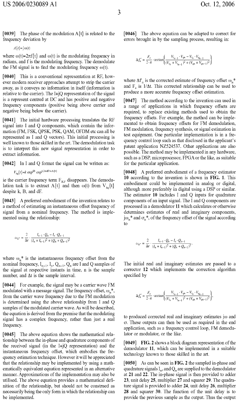
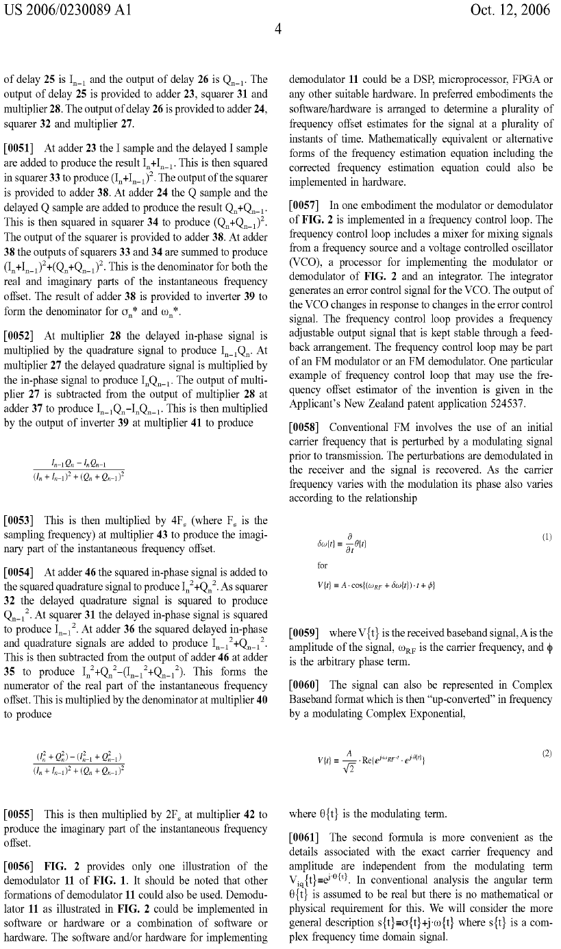
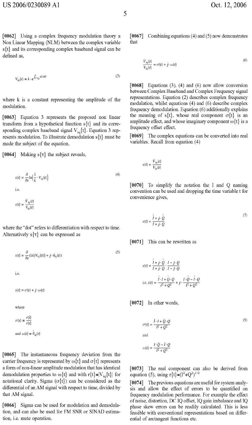
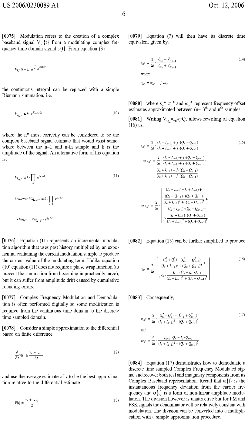
These previous pages show how the progression from exact continuous time domain representation to discrete time is accomplished. The next pages show how the resulting non linearity is predicted.
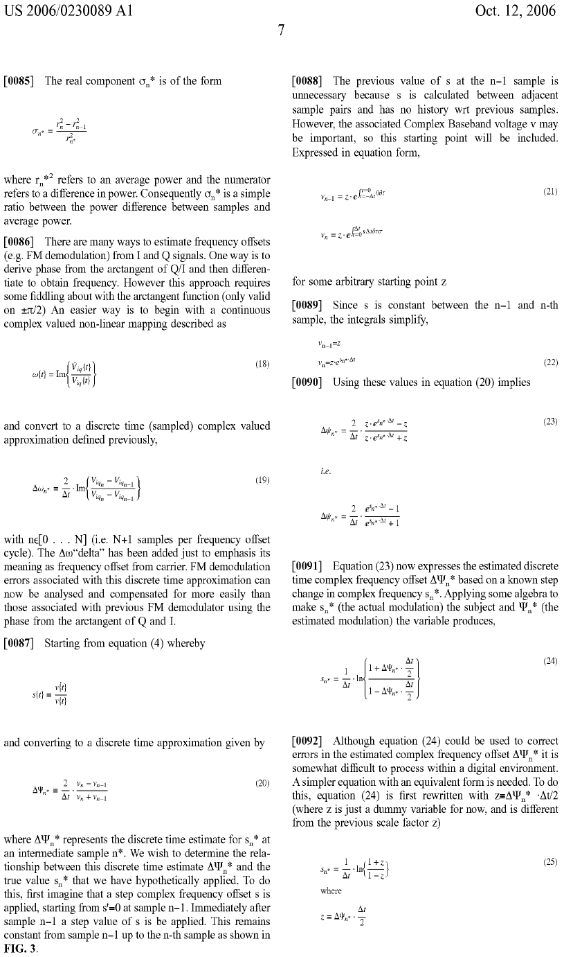
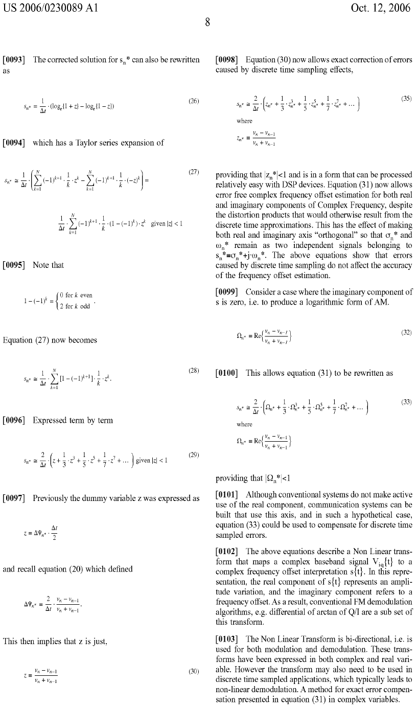
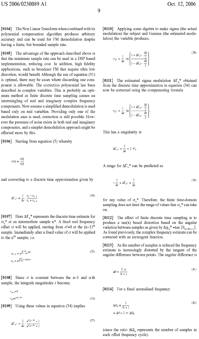
Compensation is now achieved!
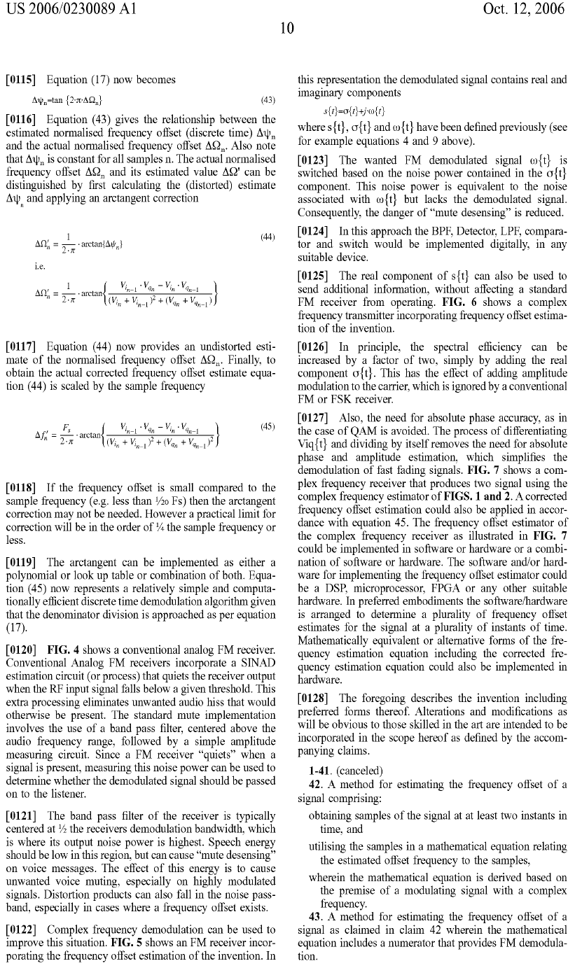
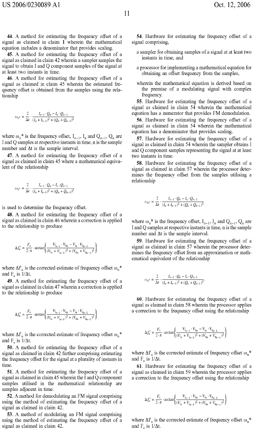
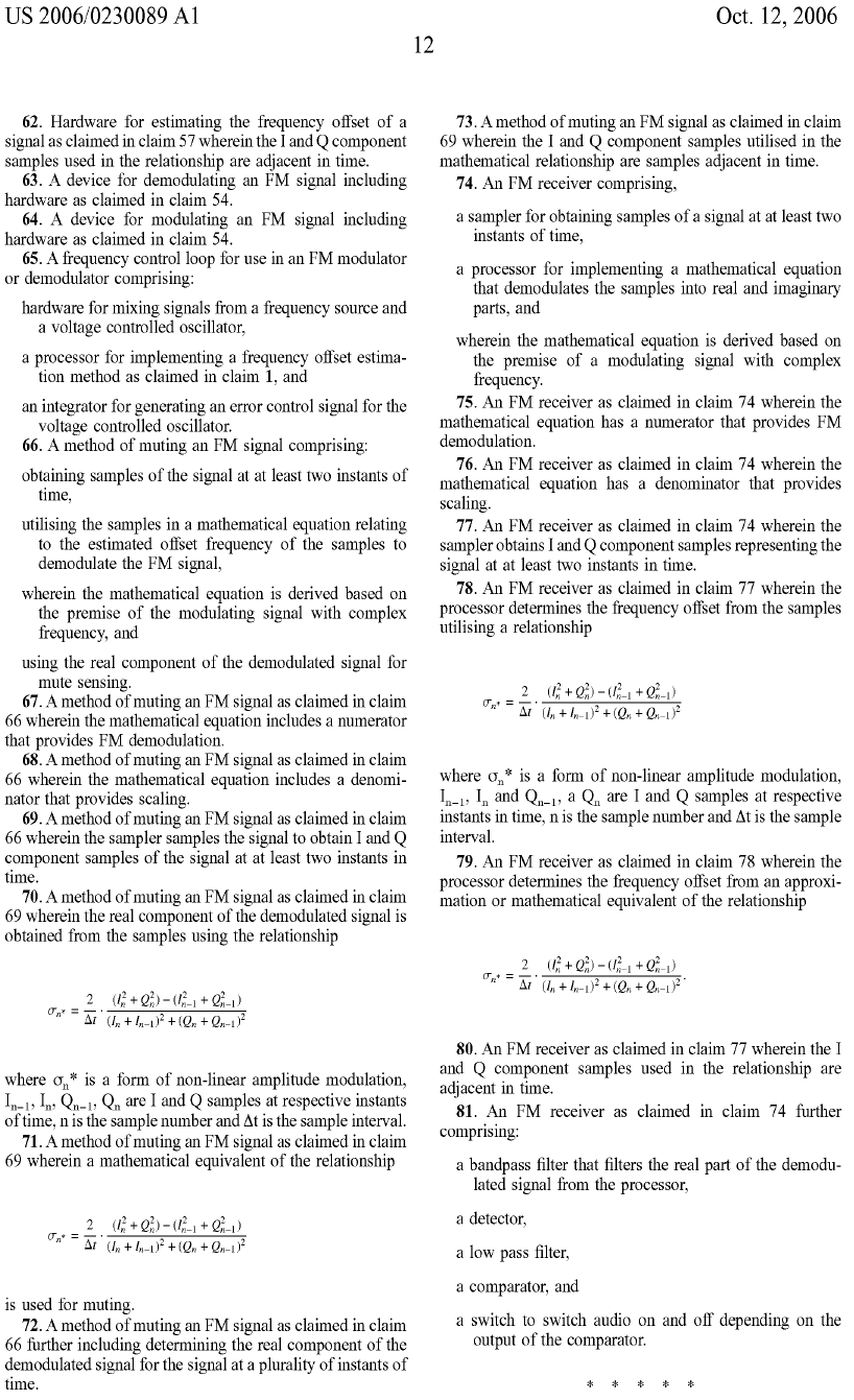
So there it is! I am quite pleased with this outcome. I hope the mathematics has been interesting to the viewer!
![]()
Return to: Ian Scotts Technology Pages
© Ian R Scott 2007 - 2008