


![]()
Resistors are used to regulate current in electronic circuits. They seem to be fairly simple beasts but in fact they have quite a few interesting properties and history.
The earliest resistors were constructed from metal substances although, in all fairness, carbon may well have been used in the first resistor implementation. This substance formed the filament of the first early incandescent light bulb said to have been invented by Thomas Edison recorded in the USA patent of 1879.

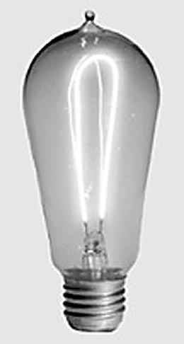

It appears however that a British inventor Joseph Swan filed a patent one year earlier and successfully won a patent infringement law suite against Edison. Even so, carbon filament light bulbs had been in use as much as 50 years previous to either patent application. Even further back an English scientist Humphrey Davy invented an electric battery in 1800 and used it to produce light from a "carbon arc". Edison's claim to fame, if any, was to produce a filament light bulb that produced light for 1,200 hours compared to today's tungsten filament lights that can last for about 1,500 hours. However, to be fair he also added many refinements required to bring the carbon filament light bulb to a commercial audience.
But I digress - such resistance resulted as a by-product in the quest to produce light as opposed to a purposeful intention for current regulation. Nichrome wire was very suitable for this purpose due to its relatively high resistance compared to other metals. The resistance R was proportional to the length of wire and inversely proportional to its cross section area. The relationship between voltage, resistance and current, commonly (and perhaps not exactly correctly) referred to as "Ohm's Law" is
V = I · R
or I = V/R
However, electronic components are seldom without imperfections and the Nichrome resistor was no exception. The first unwanted characteristic was its temperature dependence. Nichrome, as with all metals has a positive temperature coefficient and its resistance is approximately proportional to temperature
R{ T } = R{ T0 } · T / T0
where R{ T } represents resistance at a temperature T
in Kelvin, R{ T0 } represents resistance at nominal
temperature T0 (e.g. room temperature = 25° C =
298º K) and T / T0 represents a temperature ratio.
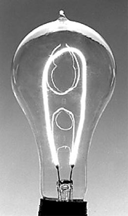
This effect is very evident in standard incandescent light bulbs  which
exhibit a relatively high "in-rush" current when first turned on due
to a cold filament, falling to a nominal value as it heats up sufficiently to
produce useful, visible light.
which
exhibit a relatively high "in-rush" current when first turned on due
to a cold filament, falling to a nominal value as it heats up sufficiently to
produce useful, visible light.
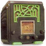
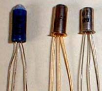
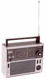
The second main problem surfaced at radio frequencies. Nichrome "wire
wound" resistors required long lengths of fine diameter wire in order to achieve
moderate to high values of resistance required by electronic valves
![]() used in early valve medium and short wave radios
used in early valve medium and short wave radios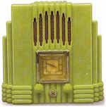
 .
. .
The most compact method used to scrunch this wire up into a smaller volume was
to wind it as a solenoid on a ceramic body. Unfortunately this structure is
exactly that as used by inductors, so the effective resistance at radio
frequencies became significantly different than the value at low audio
frequencies or DC. Consequently, wire wound resistors tended to be used for DC
applications such as to regulate the current flowing through the heating
filaments of electronic valves.
.
The most compact method used to scrunch this wire up into a smaller volume was
to wind it as a solenoid on a ceramic body. Unfortunately this structure is
exactly that as used by inductors, so the effective resistance at radio
frequencies became significantly different than the value at low audio
frequencies or DC. Consequently, wire wound resistors tended to be used for DC
applications such as to regulate the current flowing through the heating
filaments of electronic valves.
Unlike metals, carbon has a relatively high resistivity and can also be formed into thin films suitable for deposition on an insulating material such as ceramic. Further, carbon particles can be mixed with insulating materials (e.g. clay) to further increase its resistivity. This provided the wide range of resistance values required to regulate electric currents in early valve amplifiers radio transmitters and and radio receivers.

|
Colour |
Number |
|
Black |
0 |
|
Brown |
1 |
|
Red |
2 |
|
Orange |
3 |
|
Yellow |
4 |
|
Green |
5 |
|
Blue |
6 |
|
Violet |
7 |
|
Grey |
8 |
|
White |
9 |
These early resistor components were relatively stable with temperature and have significantly lower inductance than their wire wound counterparts due to their tubular, as opposed to wire spiral construction. It was quite common to "color code" their resistance value on the resistor's body as this method was easier to implement than using actual text.
As valves became smaller, resistors also shrank in size. Manufacturing processes improved and the resistor's physical construction became simplified. The end-leaded improvement soon became the dominant structure used in valve and subsequent transistor based electronic circuits.

By about the mid 1900,s, electronic circuit miniaturization began to dominate the electronic industry's primary motivations. The replacement of electronic valves with energy efficient semiconductors reduced waste heat from watts to milli-watts and provided ample opportunity for extreme component size reductions. Further, the need for rapid and high volume product manufacture demanded continual reductions in the time required to assemble products. Manual processes gave way to automated process, then components that required fewer and fewer automated processing steps were favored.
The earliest electronic products required extensive hand assembly. Although human dexterity allowed the potential for closely spaced components on ever shrinking Printed Circuit Boards (PCB's), automation was at loggerheads with this potential. Streamlined assembly processes required attention to physical tolerances and although this introduced some overall assembly size penalty, the long term future lay in automated assembly processes.
One manufacturing step that appeared unattractive concerned the need to accurately poise leaded components over a PCB and guide the component reliably towards it's lead connecting holes. Then the leads needed to be clipped of excess length prior to soldering. These two processing steps needed to go!
This is were Surface Mount Device (SMD) technology sprang forth, emerging in the late 1960's pioneered by companies such as Philips Electronics and others. Initially expensive, these components avoided connecting leads all together and soldered flat on the surface of a PCB.
SMD resistors were constructed in a similar manner as before, and could use a flat ceramic substrate (0805, 0603 etc) or retain a cylindrical body (MELF). Useful improvements in high frequency performance immediately followed, due to the removal of "stray inductance" associated with leaded wire connections.
Today's SMD resistors can be used well into the GHz region (2.45 GHz "Bluetooth" (named after Harald Bluetooth the King of Denmark, late 900's), "WiFi" etc). Small body versions such as 0603 (0.06" by 0.03" ) have a small series parasitic inductance of about 2 nH and a stray inter-electrode capacitance of about 0.2 pF.
Due to their planar placement they actually represent short, dissipative (i.e. with electrical loss) transmission lines on a PCB
Consequently, SMD resistors are much easier to model on electronic circuit simulation software than their leaded resistor counterparts. The primary physical dimensions of width W and substrate height H, combined with the substrate permittivity er determine a characteristic impedance for the resistor. A small modification can be allowed for the additional resistor height h rising to the final conducting carbon film. Further, a "composite permittivity" for combined PCB material and the resistor's ceramic body can be defined.
Resistors have two remaining imperfections - thermal noise voltage and non linearity. Thermal noise voltage is a fundamental property of any resistance so excess noise is a potential issue. This may be voltage dependant.
Thermal noise voltage increases with temperature as does thermal noise power. At room temperature (T = 298° K), thermal noise power in a 1 Hz bandwidth is approximately given in dBm1Hz as
Pn ≈ -174 dBm1Hz
The RMS noise voltage is dependant on the actual resistor values and can be calculated from
en ≈ √ [R · 10(Pn - 30 ) / 10 ] Volts in a 1 Hz Bandwidth
The RMS Voltage in other bandwidths is proportional to the square root of this measurement bandwidth BW (thermal noise is evenly distributed with frequency)
en/ ≈ √ [R · 10(Pn - 30 ) / 10 ] · √(BW)
For example, a 1 kΩ will have a thermal noise voltage equal to 1.996 nV / Hz -0.5 . The thermal noise measured in a wider audio bandwidth of say, 20 kHz will equal 282 nV = 0.282 µV
The last potential imperfection can show up in high power applications such as those uses in radio frequency transmitters. For example, resistive attenuator pads can exhibit signal non linearity resulting in harmonic energy. Some models can show 2nd and 3rd harmonic products as high as -70 dB on the fundamental input signal for throughput power levels exceeding 100 watts.
| Temperature coefficient - controlled by strategic addition of other compounds to the carbon film | |
| Parasitic lead inductance - reduced significantly through SMD technology and reduction in physical size | |
| Thermal noise voltage - but more specifically, excess noise voltage, perhaps voltage dependant | |
| Low order signal non linearity - usually only visible in very high power RF applications |
In many situations the actual value of a resistor may need to be subject to external control
| Automobile Panel Light Brightness Control | |
| Audio Volume Control | |
| Precision Voltage and Current Adjustment In Scientific Instruments | |
| Motor Driven Servo Feedback Systems | |
| Preset Factory Adjusted Internal Settings Required To Compensate For Other Component Tolerances |
A Rheostat is a two terminal variable resistor and has a resistance value that is proportional to angular rotation. High current versions tend to be wire-wound and are used for adjusting current flow in DC circuits such as those found in some older automobiles.
A Potentiometer is a three terminal device with a "middle contact" provided as a adjustment along the physical length of a resistive element. This middle contact "taps off" a proportion of the voltage applied to the two end terminals.
Potentiometers are provided with a "linear taper" and a "logarithmic taper". Linear tapered potentiometers produce an output voltage that is proportional to angular rotation (or linear distance for "slider type" potentiometers). Logarithmic tapered potentiometers produce a pseudo logarithmic output voltage with respect to angular rotation and are used specifically for audio power control. The pseudo - logarithmic adjustment is intended to mimic the perceived sound loudness characteristic of the human ear which is also logarithmic. The actual pseudo - logarithmic characteristic is usually obtained by using a split resistive track with one section having a different resistivity compared to the other, resulting in two rates of resistance variation.


Potentiometers are intended for low power applications, unlike rheostats intended for high current control with an emphasis on removing internal heat.
 An excellent image copied from Wikipedia on the subject of rheostats
Small present variable resistors are also used in electronic circuits were component tolerances are sufficiently poor to demand factory adjustments. (In the interest of "Design For Manufacture or DFM such human intervention is considered as poor design).
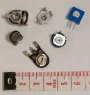 Another
image showing conventional "preset" resistors from Wikipedia
Another
image showing conventional "preset" resistors from Wikipedia
These Integrated Circuit components are now extremely popular and used in a wide range of electronic products. They are offered with digital step control and provide accurate and well defined characteristics. Unlike their manual logarithmic potentiometer counterparts, a "proper" logarithmic step is possible rather than a piece-wise dual linear taper approach.
The step resolution ranges from 32 step (5 bits) to 1024 steps (12 bits) in commonly available offerings. The use of an IC implementation provides excellent opportunity for integrating many other electrical functions as these examples from Maxim-ic testify

The DS3501 combines an internal temperature sensor with the electronic potentiometer resulting in a fully integrated output voltage dependent on temperature. The specific relationship is software programmable as shown. This represents a favorable improvement in flexibility over previous mechanical implementations.
The following DS3908 dual electronic potentiometer with digital adjustment and integrated internal buffers surely speaks for itself!
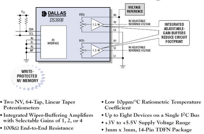
The digitally controlled potentiometers have many applications. They can even be used as low to medium speed DAC's and are available as a low cost alternative in such applications.
Light Dependant resistors (LDR) use Cadmium Sulphide or Cadmium Silenium compounds to produce a two terminal resistance that falls in value with light illumination. The relationship between optical power and terminal resistance is fairly non linear but the optical spectral response is similar to that of the human eye, i.e. having a maximum "spectral peak response" centered at an optical wavelength around 550 nm (green light).
These components were among the first optical receiving devices and were used to produce audio from optically encoded movie sound track in picture theaters. They are relatively "slow" and therefore not suitable for high fidelity applications based on today's stringent requirements.
In this web chapter I have introduced the humble resistor in all its glory. I hope the small amount of history was of interest. Often overlooked as electrically unimportant, the resistor has actually had a varied background beginning with legal patent battles over the carbon filament light bulb, culminating now in the highly refined SMD construction.
The story need not end here of course - resistors are also fabricated on silicon substrates as required by integrated circuits. Others are intended to allow variation through manual adjustment, others can be controlled electronically as with digital potentiometers
The only resistor I think I have (purposely) missed are "carbon microphones". I'm sure some future archeologist will uncover one of these along-side the low fidelity tolerant ear of a dinosaur.
![]()
Return to: A Component Universe
or: Ian Scotts Technology Pages
© Ian R Scott 2007 - 2008