
![]()
Electromagnetic
waves or “radio waves” have an number of associated physical constants that
are used to describe their properties. We will consider radio signal propagation
in a vacuum (i.e. “free space”) for now. We will also assume “line of
sight” propagation from an energy radiating radio source antenna (i.e. a
transmit antenna) to an energy absorbing electromagnetic load (i.e. a receive
antenna). This approach allows basic relationships to be established initially
and then the real world imperfections to be included as modifications later on.
The
first physical constant is generally called the “permeability of free space”
identified as the Greek letter μ0 and related to magnetic
properties. This physical constant is a defined coefficient and has a
value defined as
![]() …(1)
…(1)
This
value is used as a reference for many other related constants that can be
determined by experiment (i.e. μ0 can be thought of as a
scaling factor) and has a numerical value of
![]() …(2)
…(2)
to 4
significant figures in units of Webers per Amps per meter. Also, the permittivity
of free space labeled as the Greek letter ε0
has an experimentally determined numerical value of
![]() …(3)
…(3)
also to
four significant figures in units of Coulombs-squared per Newton per meter.
Permeability and permittivity are related to the speed of light c
according to
![]() …(4)
…(4)
The value of c in a vacuum measured to 5 significant figures is
![]() …(5)
…(5)
This
(theoretical) relationship between permeability μ0, permittivity
ε0, and the speed of light c implies that one
coefficient needs to be defined and then the other two coefficients are
“scaled” to suit this definition. This is no different than choosing a
measure of distance as “meters” or “feet” or “cubits” etc and then
measuring “length” in terms of such a reference unit. It is current practice
to choose the “permeability of free space” μ0 as this
“pivot” coefficient and therefore reference other measured coefficients
against this defined value.
It is
also useful to introduce another term or concept called the “impedance of free
space” that we will label as Rελ .This term is
defined to have a value also related to permeability μ0
and permittivity ε0
defined as
![]() …(6)
…(6)
The
impedance of free space has a value to four significant figures of
![]() …(7)
…(7)
Note:
The value of Rελ can also be expressed in terms of μ0
and ε0 from equations (5) and (6) as Rελ = μ0 ּ c
The
impedance of free space Rελ can now be used to
predict a relationship between the magnetic field component H and the
transverse electrostatic component E in an electromagnetic wave
propagating in free space. These radio signals components have RMS magnitudes
related by
![]() …(8)
…(8)
This
is analogous to Ohms Law for voltage, current and resistance.
![]() …(9)
…(9)
We have
similar energy predictions for these electromagnetic components. Let us use S
to represent “energy density” in units of watts per square-meter i.e. W m-2
.The energy density S can be determined from either the magnetic
component H or the electrostatic component E as
![]() …(10a)
…(10a)
or
equally
![]() …(10b)
…(10b)
The
total power Pr, total
flowing through an arbitrary surface is equal to the integrated
power density S over this surface. Providing that no other losses (such
as heat, light etc) are present, the total power Pr, total
flowing through a surface that totally encloses a radiating
source will equal the power supplied to the radiating source. Although the size
and shape of this surface does not affect the total integrated power (in free
space without propagation losses as in a vacuum) it is mathematically convenient
to define a surface shape that is familiar and convenient to work with. The most
common surface shape is spherical and a given point z on its surface can
be defined in polar co-ordinates in terms of a radius d,
a horizontal angular position θ and an vertical angular
elevation Φ so that z ≡ zd,
θ ,Ø.
This
polar definition implies the following limits of 0 ≤ d
< ∞, 0 ≤ θ
< 2 ּ π and -π \ 2 ≤ Φ
< π \ 2 .
This polar co-ordinate system now allows us to predict the total
electromagnetic power flowing through the surface of this imaginary sphere from
a radiating source as a double integral defined as
 …(11)
…(11)
where
![]() represents the electromagnetic
energy density at a distance d from a radiating source placed at the
origin of this sphere and at a horizontal angular position θ and
with a vertical angular position Φ. We will drop the subscripts on S
in further equations for convenience i.e.
represents the electromagnetic
energy density at a distance d from a radiating source placed at the
origin of this sphere and at a horizontal angular position θ and
with a vertical angular position Φ. We will drop the subscripts on S
in further equations for convenience i.e.
 …(12)
…(12)
If the
energy density S is constant over the surface of this sphere then the
integral simplifies to equal the energy density S multiplied by the
surface area of this sphere i.e.
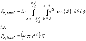 …(13)
…(13)
A
hypothetical antenna that produces a constant energy density over the surface of
a sphere originating from its position is called an “isotropic antenna”.
Given that we generally accept that energy cannot be created nor destroyed, the
total power applied to a transmitting isotropic antenna results in an equal
total power flowing through the surface of such a sphere (or any other closed
surface surrounding the transmitting antenna as previously mentioned). This is
true for any antenna unless unwanted parasitic power loss mechanisms are
present, for example power lost in conductor resistance or surrounding
dielectric materials with dissipative loss.
It is
useful to predict the propagation power loss between a transmitting antenna and
a receiving antenna separated by a
distance d. Two isotropic antennas are typically used and form a
basis for comparison with other antenna types. Since we immediately know that
the power density Sd is equal to the transmitted power divided
by the surface area of this sphere, the power received by an isotropic antenna
will be proportional to its “effective receiving area” or aperture area.
The size
of this aperture area depends of the wavelength λ of the electromagnetic
radiation received and is usually considered to be given by
![]() …(14)
…(14)
We also
will note that the wavelength and frequency of electromagnetic wave in free
space is
![]() …(15)
…(15)
The free
space propagation PowerRatio between received power and transmitted power is
simply equal to a ratio of aperture area to the area of this imaginary sphere
i.e.
 …(16)
…(16)
When
this loss is expressed in decibels (i.e. LossdB ≡ -10 •
Log10 { PowerRatio } ) as
a positive loss quantity we arrive at the well known “Fris Equation”
![]() …(17)
…(17)
The
isotropic antenna is used as a “reference” for comparison with other antenna
that may exhibit a useful relative power gain GdBi
(directional antennas) or a relative power loss (usually exhibited by compact or
electrically small antennas) as a figure of merit.
A purely
isotropic antenna is only a hypothetical concept and is theoretically impossible
to construct in the “real world”. However these isotropic antennas can be
used to form a reference path loss prediction. When substituted with two
identical real antennas the measured path loss will be different.
If the
loss is lower, the substitute antennas are said to have a power gain, shared
equally between each. For example, if a measurement distance is chosen and the
predicted path loss for isotropic antenna is 50 dB, for example, and the
measured path loss for two real, identical antennas is only 45 dB, then the
combined antenna gain GdBi is 5 dB. Since the gain is shared
equally for transmit and receive antennas it follows that each antenna gain is GdBi
= 2.5 dB in this example.
Antenna
gain or loss performance can therefore be measured in reference to other known
antennas. However this comparison gain is affected to some extent by the
separation distance d between the transmitting and receiving antennas. If
the separation distance is too small, the comparison gain estimate will exhibit
an error. Conversely, if the distance is to great the propagation loss may
result in received power levels that are far too low to measure accurately.
There is
some requirement therefore to define some “transition” distance between
“too close” and “too far”. The transition is usually described as
“near field” radiation for small separations and “far field” radiation
for large separations. The actual transition distance is “fuzzy” and depends
on the actual antennas used, but a general guide is that
![]()
In
practice, real antenna measurements are readily performed sufficiently in the
far field without unwanted errors introduced and with ample available signal
strength energy received.
Now let’s illustrate the previous concepts diagrammatically,
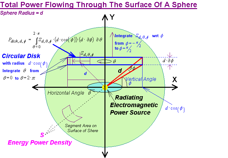
We
consider an arbitrary transmitting antenna radiating electromagnetic energy that
is dependent on direction. Let us define a polar co-ordinate system with the
transmitting antenna placed at the origin. The distance from this origin
to a point on the sphere’s surface is equal to the radius d of this
imaginary sphere and has a horizontal angular position
![]() and a vertical
angular elevation
and a vertical
angular elevation
![]() . As previously mentioned, 0 ≤
. As previously mentioned, 0 ≤
![]() < 2 ּ π and -π \ 2 ≤
< 2 ּ π and -π \ 2 ≤
![]() <
π \ 2.
<
π \ 2.
The power density
![]() at this point on the surface of
this sphere is proportional to the power Ptx supplied to the
transmitting antenna its radiation pattern. For this analysis we will consider that dissipative
power losses are not present so that the antenna efficiency = 100 %. (Any
unwanted losses can be added later to represent less than ideal real antenna
performance).
at this point on the surface of
this sphere is proportional to the power Ptx supplied to the
transmitting antenna its radiation pattern. For this analysis we will consider that dissipative
power losses are not present so that the antenna efficiency = 100 %. (Any
unwanted losses can be added later to represent less than ideal real antenna
performance).
The total integrated power can be predicted by first predicting the power
flowing through a circular horizontal cross section disk of this sphere i.e.
 …(18)
…(18)
We can see that this circular disk having a vertical elevation defined by
ø has a radius r = d
· cos{ ø } and infinitesimal thickness w = d · ∂ ø.
Its surface area is therefore equal to the integral of r · w = d 2
· cos{ ø } ∂ ø wrt
the horizontal angular position
![]() . We can represent equation (18) a bit more elegantly as
. We can represent equation (18) a bit more elegantly as
 …(19)
…(19)
Now that we have determined the total power flowing through the surface
area of this circular cross section, the total power flowing through the surface
of the sphere requires an
additional integration wrt the angular elevation
![]() leading to
leading to
 …(20)
…(20)
How
to Determine Radiation Resistance 1
The power supplied to the transmitting antenna can be stated as
![]() …(21a)
…(21a)
were Irms2 represents the RMS current
flowing into the antenna’s input connections and Ra refers
to its “radiation resistance”. This radiation resistance refers to a real
load that converts electrical input power into electromagnetic radiation in the
same way that a resistor converts electrical energy to heat. Although a real
antenna will also have a frequency dependant series reactive component, this
reactance can always be removed by adding an equal and opposite series reactive
component (we always assume that an antenna is properly “matched” to its
power source for predicting its characteristics).
The input power can also be expressed relative to a parallel equivalent
radiation resistance and a RMS voltage applied to its input connection
![]() …(21a)
…(21a)
In this case Vrms2 represents the RMS
voltage applied to the antenna’s input terminals and R/a
refers to the antenna’s parallel “radiation resistance”. Any reactive
component is cancelled by connecting an equal and opposite parallel reactance
across the antenna terminals.
We know that a loss-less antenna will radiate all its electrical input
energy as electromagnetic energy without (losses wasted as heat) so that
![]() …(22)
…(22)
We can therefore write
 …(23)
…(23)
were
![]() or
or
![]() .
.
If we replace Ptx as defined in equation (21a) and make
the radiation resistance Ra the subject we arrive at
 …(24a)
The actual radiation resistance will depend on the radiation pattern
described by its radiated energy Sd,θ,Φ for a given
RMS input current Irms .Alternatively, the parallel form of
antenna radiation resistance R/a could be used if
applicable
 …(24b)
Equation (24a) (and potentially (24b)) provide an immediate solution for
the radiation resistance Ra of a dipole antenna providing that
the radiated energy density pattern Sd,θ,Φ = S{
Irms, d, θ, Φ } is known.
The usual derivation procedure for determining the energy density pattern
Sd,θ,Φ is to first predict the magnetic field
strength
![]() resulting from a RMS AC current Ix
flowing through each incremental length of radiating conductor relative to some
reference point x along its length and at a distance in polar coordinates
defined in terms of d, θ and Φ. Although the
shape of the conductor is not important, simple geometries result in simple
mathematical expressions and are therefore preferred. The simplest geometry is a
straight conductor e.g. a wire, with an distance dependant AC current Ix
flowing along its length.
resulting from a RMS AC current Ix
flowing through each incremental length of radiating conductor relative to some
reference point x along its length and at a distance in polar coordinates
defined in terms of d, θ and Φ. Although the
shape of the conductor is not important, simple geometries result in simple
mathematical expressions and are therefore preferred. The simplest geometry is a
straight conductor e.g. a wire, with an distance dependant AC current Ix
flowing along its length.
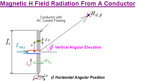
If we assume a straight vertical conductor then we can predict the
radiated magnetic field
![]() produced by a position dependant
current Ix flowing in each incremental length element
produced by a position dependant
current Ix flowing in each incremental length element
![]() at a distant point in space
relative to this polar coordinate system as
at a distant point in space
relative to this polar coordinate system as
 …(25)
…(25)
This magnetic field intensity
![]() is constant with respect to the
horizontal angular position
is constant with respect to the
horizontal angular position
![]() . The total magnetic intensity is equal to the vector sum of all incremental
magnetic field contributions at this distant point. We therefore need to
integrate these incremental field contributions
. The total magnetic intensity is equal to the vector sum of all incremental
magnetic field contributions at this distant point. We therefore need to
integrate these incremental field contributions
![]() over the length L of the
conductor
over the length L of the
conductor
 …(26)
…(26)
We can now predict the energy density
![]() at this distant point from the
magnetic field intensity
at this distant point from the
magnetic field intensity
![]() magnitude
using equation (10a)
magnitude
using equation (10a)
![]()
i.e.
 …(27)
…(27)
Substituting equation (27) into equation (24a) results in
 …(28)
…(28)
Equation (28) provides a generic prediction tool for radiation resistance
Ra for any center fed dipole antenna. The distance term d is
constant for a sphere and might be predicted to cancel (an advantage for the
polar coordinate system as opposed to a Cartesian coordinate system!) but beware
– this assumption may be premature!
Although the distance from the center of this radiating conductor is
constant, this is not true over the length of the radiating conductor – i.e. d
depends to some extent on x. Although this “modified” polar distance d/
will have a decreasing effect on the magnitude of the magnetic
field intensity as the distance d/ increases, the associated phase
shift caused by propagation time delay will remain unchanged and will
affect the integration outcome. This is why the distance term d will not
be removed from inside the inner integral just yet!
We can however reasonably expect that the AC current term Irms
will disappear if we define a relative AC current
![]() as
as
![]() …(29)
…(29)
The final solution for radiation resistance Ra is now
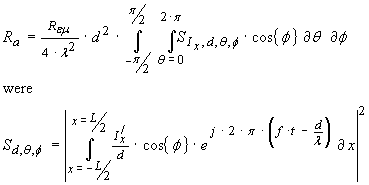 …(30)
…(30)
It should be pointed out that the relative current distribution
![]() in the radiating conductor is a
vector quantity with magnitude and phase components so that the total magnetic
field at a given point in space is the result of the vector summation of all
vector contributions from all incremental radiating elements of the conductor.
The total power over a surface however is the result of a scalar integration
over all points were the total magnetic field density has been evaluated.
in the radiating conductor is a
vector quantity with magnitude and phase components so that the total magnetic
field at a given point in space is the result of the vector summation of all
vector contributions from all incremental radiating elements of the conductor.
The total power over a surface however is the result of a scalar integration
over all points were the total magnetic field density has been evaluated.
The
magnetic field strength H caused by an AC RMS current Ix
with a sinusoidal frequency f = c/λ
flowing in an “short” conductor element with length δx at a distance d and vertical angular elevation
![]() is predicted from
is predicted from
 …(25)
…(25)
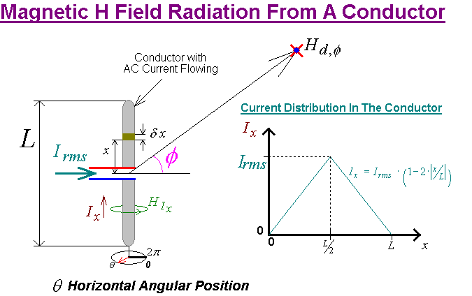
We will
define the vertical position of a point x on this conductor to be x
= 0 at its center electrical input and x
= ±L / 2 at its extremities. Now let’s define
the total length as a proportion of a half wavelength i.e. L ≡
γ · (λ
/ 2).
 …(26)
…(26)
We will
first assume a linear current distribution Ix in the radiating
dipole elements that has a maximum RMS value of Ix = Irms
at the antenna’s center input connection falling to Ix = 0
(zero current) at the ends. Since the dipole is considered to be electrically
short compared to a half wavelength we also will assume that the current flowing
in each length segment δx
remains in phase so that
![]()
Ix
= Irms ·
(1 -
| 2 · x /
L | ) were
-L / 2
≤ x ≤ L
/ 2 and
L ≡ γ
· λ / 2
The
integral identified in equation (26) becomes

Substituting
this result into equation (6) predicts the magnetic H field for an electrically
short dipole to be
 …(27)
…(27)
From equation (10a) we had
![]() …(10a) where the magnetic field H
was presented as a magnitude. This allows equation (27) to be rewritten as
…(10a) where the magnetic field H
was presented as a magnitude. This allows equation (27) to be rewritten as
 …(28)
…(28)
We can
now substitute the predicted energy density Sd, into equation (24a)
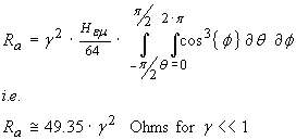 …(29)
…(29)
Equation
(29) predicts the radiation resistance Ra for a dipole antenna
that is electrically short compared to a half wave dipole (i.e. γ << 1). This radiation resistance falls to low values as the antenna length
reduces and will have an additional capacitive series reactance –j · Xs
that will have an increasingly high
value. This will need to be “resonated” with a corresponding positive
inductive reactance at a given operating frequency f but the high
resulting Q = Xs / Ra will result in a narrow band
frequency characteristic.
MathCAD Example
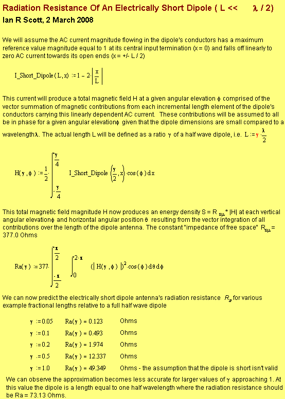
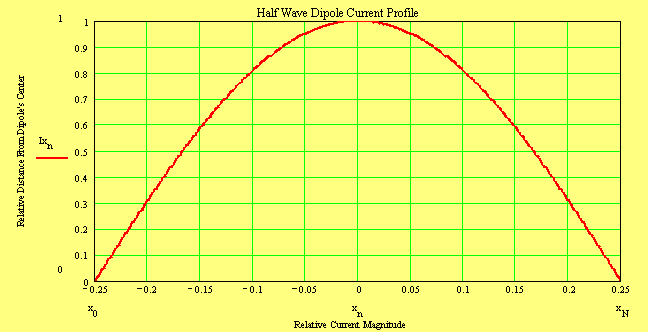
The previous electrically short dipole becomes a half wave dipole when
γ = 1 but the current distribution will change from a linear relationship to
a cosine one, i.e.
Ix
= Irms ·
cos{ 2 · π · x / λ ) were - λ
/ 4 ≤ x
≤ λ
/ 4 …(30)
Since the half wave dipole is now
physically large compared to a wavelength we will need to consider a
“propagation delay” corrective term.
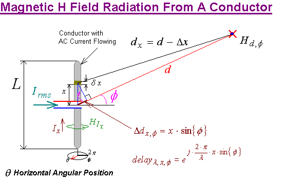
This
half wave dipole is (by definition) physically large compared to a wavelength
resulting in a small path length difference Δx between magnetic
field contributions created by current flow in each incremental conductor
length. Although this small path length difference will not change the magnetic
field appreciably (since far field prediction is assumed i.e. d is
large), the propagation time delay caused by this path difference will result in
a phase shift from field contributions arising from different positions x on the
dipole.
![]() …(31a)
…(31a)
were
![]() …(31b)
…(31b)
This
time delay results in a phase correction term that can be applied to the
incremental magnetic fields as a multiplicative term prior to integration
![]() …(32)
…(32)
Each
incremental magnetic field contribution hλ,x,d,Φ
at a distant polar position (d, θ, Φ) has
magnitude and phase components to account for, therefore
 …(33)
…(33)
The
total magnetic field magnitude at (d, θ, Φ) becomes
 …(34)
…(34)
Recall
equation (30) and this time we understand that the integration distance d = d{x},
restated below as
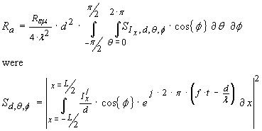 …(30)
…(30)
Substituting
equation (34) into equation (30) results in the final prediction for radiation
resistance Ra
 …(35)
…(35)
I tried
to compute this integral numerically on MathCAD and obtained the following
prediction for radiation resistance using an arbitrary wavelength parameter
λ
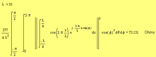
We can
see that the λ term will cancel after the inner integration is performed.
The
![]() constant will also appear as a
scaling term after this inner integration so will be taken outside the
expression. This leads me to
simply state a simplified, wavelength independent expression to now be
constant will also appear as a
scaling term after this inner integration so will be taken outside the
expression. This leads me to
simply state a simplified, wavelength independent expression to now be
 …(36)
…(36)

Yes, MathCAD is a great program for checking the maths!
![]()
Return to: Antenna or use your browser's "back button"
or return to: A Component Universe
or: Ian Scotts Technology Pages
© Ian R Scott 2007 - 2008