
![]()
Isaac Newton provided the notion that "every action has an equal and opposite reaction" and although this comment can be interpreted either as a maxim or a quip, I consider it to be commonly misinterpreted.
I am interested in how to travel in space for example - Isaac's proviso stands in the way of this a bit. A rocket, for example, throws mass out behind it's line of travel in order to accelerate forward, commonly assumed to be the only mode of acceleration possible. The force required to eject mass behind the rocket, equals, as Isaac says, the force acting on the rocket in the forward direction causing it to accelerate and therefore gather speed.
This is a dismal approach of course as eventually all mass will be lost to space! It doesn't matter (oops a bad pun) if this mass is ejected as carbon burnt fuel, ions from a nuclear "furnace" or photons from a laser or equivalent (especially as laser energy conversion efficiency is extremely poor) still result in a net loss of rocket mass. This clearly can't go on forever.
It is certain that mass is precious is space, and although it can be collected in a "ramjet" approach and used for propulsion, this method would be unsuitable for low speed navigation and high acceleration maneuver's such as those needed near a planet's surface.
Simple "rectilinear motion" cannot result in forward acceleration. For example if you stand on ice and throw a heavy ball forward you will travel backward. Let's say the ball is attached to you with by a rope. The rope will unwind and eventually become taut. It will then exert an equal force and opposite to the force felt by you and it will return as will you to the same exact spot (assuming no friction).
This is the argument used to dismiss any possibility other than the conventional method of wasting mass for propulsion. Many people, including those with famous minds, have analyzed "rectilinear accelerated masses inside an inertial frame" and found, not surprisingly, that no net acceleration is possible. I would have thought this obvious myself, but once again they fail, in their imagination, to ask the better question
"How can we make this work?"
Hopefully the mind of an amateur scientist is better equipped to solve a problem rather than much simpler approach of mere dismissal.
In many ways those that argue against the possibility of obtaining net acceleration from operations inside a closed vessel rely on their credentials as great scientists or mathematicians to justify their inability to solve a problem. I guess the most appropriate fable that springs to mind is the story of "The Emperor's New Clothes". To recall, in this fable the Emperor is duped into buying a set of "invisible clothes". He puts them on and goes outside to address his kingdom. But because he is the Emperor (e.g. scientist, mathematician) the people will not tell him he is naked. Some will actually see him fully clothed, others will be too afraid to tell. The a young child shouts out "The Emperor has no clothes!" and the illusion is shattered.
In this web chapter I will show how simple it is to solve the problem of propulsion with conservation of mass. This is clearly necessary for any long distance space travel with equal capability for flight near a planet's surface.
As I said, the concept is simple. Consider this thought experiment - you can do it yourself even on an ice skating rink.
Let's say you stand on this ice and you hold a heavy metal bar to your chest and horizontal to the ground. Pull the metal bar towards you and you will move forward as the heavy metal bar goes behind.
Now rotate ½ a turn. (This is what the people who studied this issue failed to imagine)
The heavy metal bar is still behind you so push it forward from your chest and you will move backward.
Because you are facing the other way now you continue to move forward relative to your surroundings as before.
Note that you and the heavy metal bar are now at the same position relative to each other as when you started.
Now complete the full rotate-a-turn. This provides no acceleration of course but returns you to your original angular position
So obviously you can repeat the maneuver. Repeat "pull the bar in", "rotate ½ a turn", "push the bar back out" and you will continue to move forward.
Now complete the full rotate-a-turn.
You can do this indefinitely without any loss of mass.
So it is simple that "rectilinear motion" combined with "circular motion" can produce a net "forward thrust" without any loss of mass - after all the heavy metal rod stays firmly in your hands as you accelerate over the ice (No mass is lost unless you have lost some weight from the exercise!)
Imagine a ball (black) connected to a rod that is tied at the center of x-y co-ordinate axes. This is position 1.
If the ball is pushed upwards as shown an equal and opposite force will indeed occur in the downward direction as in position 1.
Now rotate clockwise half a turn.
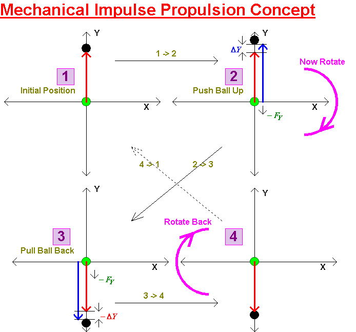
The ball remains "outstretched" in position 3 so it can be pulled back to its original position to arrive at position 4. This creates an equal and opposite force. Note that this force is also in the "down direction" because of the rotation by 180 degrees. This is certainly not difficult to visualize.
From position 4. now complete the rotation back to the starting direction. We note that two impulse forces have acted downward. Clearly these add (without the half turn they obviously would subtract - people have failed to add a simple half turn in their analysis)
Given that the ball is back to position 1 exactly as before the process can be repeated.
If the apparatus is pivoted on a frame a net downward force will be observed. If the frame is let go, the frame will move (it doesn't have to point downward - put it on a level surface). If the process is repeated the frame will move continuously and continue to accelerate.
Energy needs to then be supplied. The ball and rod and the rotation both need a source of power but note - no mass is lost. The apparatus can be completely enclosed with an internal battery and placed on ice.
Now the "impulse" per se, is not really the mechanism, it is just used to explain the mechanism. In practice the ball will move backwards and forward in a sinusoidal manner. The acceleration forces will vary in the x and y directions and have maxima along the y axis and minima along the x axis. Equally, the circular motion will be constant.
The use of simple sinusoidal motion will help "smooth out" the propulsion and also allow a resonant restoring force for the accelerated mass (i.e. "a ball on a spring"). This makes the mechanical drive requirements a lot easier.
One point worthy of note. If you point the apparatus upwards it will tend to levitate. As the speed of rotation increases it will rise above the ground. If its position is kept stable at a fixed rotation it will not use energy.
This is not surprising. A mass resting a table does not use energy so why should this concept be any different? Energy is only needed when the apparatus rises as its potential energy is increased. Equally when it falls, energy is given out.
I hope this explanation is helpful. As can be seen it was not at all difficult to imagine. However a practical impulse engine will benefit from some refinement. I will explain these in the next section.
Let us return to the previous diagram. This showed a clock-wise rotation. Although equal and opposite angular motion should be preserved, so that no net rotation happens, there is a danger that the apparatus will tend to veer to one side as it travels forward. What will happen if we reverse the rotation?
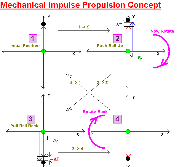
Lets consider the ball starts in the same position and this time we rotate counter-clockwise.

As can be seen the forces remain in the downward direction. The direction of rotation has no effect, as long as a rotation is provided, the two forces remain in the same direction and add.
It seems obvious therefore to combine two impulse engines, one with a clock-wise rotation and one with an anti-clockwise motion. This will cancel any tendency for a net overall rotation in the co-joined apparatus.
I will just represent each apparatus as symbols now for convenience.
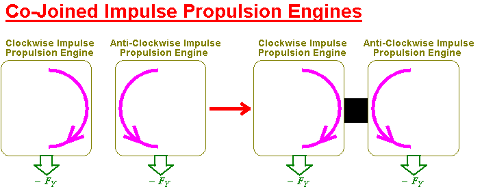
This co-joined impulse engine pair is a two phase system. Although sinusoidal motions will be used it may still result in a bumpy ride. Just as high power electrical systems use 3 phase voltage, the same principle can be used here. The vector addition of all 3 co-joined impulse engines will be the same but any ripples in the acceleration will be nicely smoothed out.
I will use the following symbols to represent single impulse engines, a two phase impulse engine and a 3 phase impulse engine.
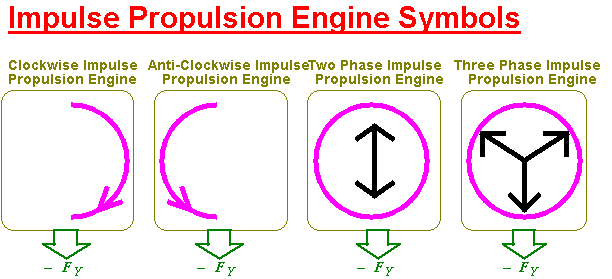
Certainly, any number of phases can be used in a multi-phase approach leading to an even smoother ride.
If it were me, I'd tie two 3 phase impulse engines together. One would provide levitation and the other would provide forward motion.
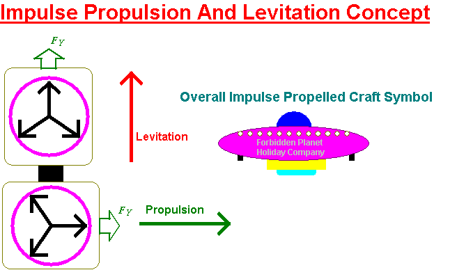
Then I'd probably, oh, put them inside some sort of a saucer shaped thing and buzz the natives.

I hope my web chapter has dispelled the myth that levitation and propulsion requires the loss of mass (or in the case of conventional aircraft, the need to waste energy just to stay in the air). The trick is simply to combine rectilinear motion with rotation at the same sinusoidal frequency and it's all a done deal.
I admit I had quite a lot of fun drawing the diagrams this morning. I have to go to the bank now and withdraw some cash to buy a few components.
![]()
Return to: Conjecturals
or Ian Scotts Technology Pages
© Ian R Scott 2007 - 2008